Is Your Electrical Contractor Qualified to Install Solar?
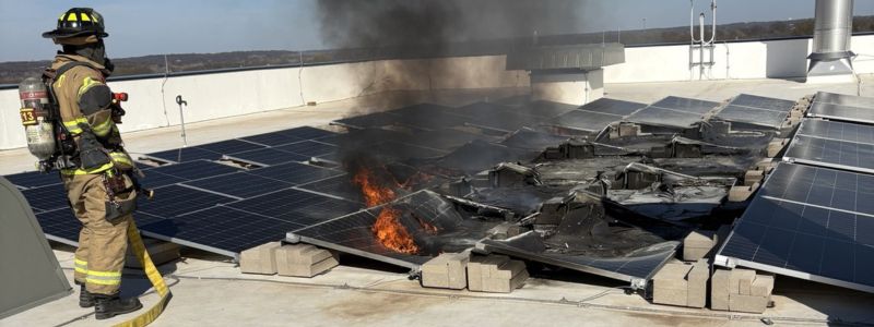
This is a reasonable question for a General Contractor (GC) to pose to any solar subcontractor. In April of this year, a long-term GC client of the Solar Design Studio contacted us to investigate the cause of a 100 KW rooftop solar array fire on a newly constructed commercial building. Fortunately, the damage to the roof was limited to the area directly under 5 rows.
A Case Study of a 100 KW Rooftop Solar Fire: What Went Wrong?
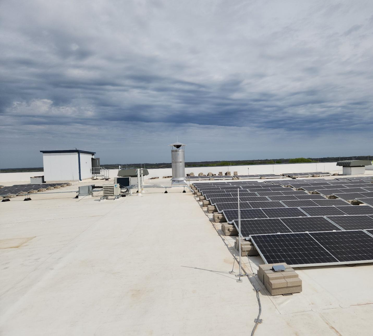
The ballast-mounted system was constructed with solar equipment from well-known manufacturers and included 180–545 Watt Modules, 2 50 kW 480 Vac Inverters, and 90 2:1 Rapid Shutdown Devices (RSDs). The solar array was installed by a local Electrical Contracting (EC) firm that had been in business for more than 50 years and was also the building project’s EC.
The fire occurred in the afternoon on a sunny, clear day, approximately two weeks after the system was installed and inspected by the local AHJ and approved by the utility.
Contributing Factors to Solar Array Fires: Insights from the Investigation
Initially, we reviewed documents prepared by the EC, which utilized the “5 Whys Methodology” and included post-fire event thermal imaging, commissioning findings, weather data, and photographic evidence. The EC’s investigation report did not conclusively identify a single cause, only the following contributing factors:
- Post-fire thermal imaging shows multiple hotspots, suggesting thermal stress.
- System energization timeline aligns with the first full-sun exposure on the day of the incident.
- A commissioning wiring inconsistency was identified: all strings were connected to MPPT1 rather than being distributed across the three MPPTs, which may have increased localized electrical stress.
- The lack of a documented shading analysis prior to installation leaves open the possibility of shading-induced hotspots.
- Post-fire photographs indicate structural shading from rooftop equipment contributed to localized heating.
- The manufacturer's installation manual explicitly warns against permanent shading, noting it can lead to module defects and void the warranty.
The investigation report emphasized these factors as potential contributors rather than confirmed causes. Specific to the thermal imaging, the report’s author concludes the images supported the hypothesis “That rooftop equipment shadows contributed to localized heating of modules. This likely accelerated hot spot development and ignition, particularly under full sun exposure following system energization.” At the completion of the investigation, shading and hot spot development did not cause the fire and was a non factor.
Investigating Electrical Mistakes: Wiring Inconsistencies and Their Impacts
The following items were absent from the EC’s investigation report:
- Solar PV experience of the individual who prepared the investigation report
- Solar PV installation experience of the EC’s solar installation
- Quality of workmanship
- Reference to the site survey shade analysis report
- Commissioning report
- Issue with the construction documents, which were not prepared or provided
- “As Built” documentation
Our next step included a site inspection and interviews with the construction management team.
The following observations were made during the site inspection:
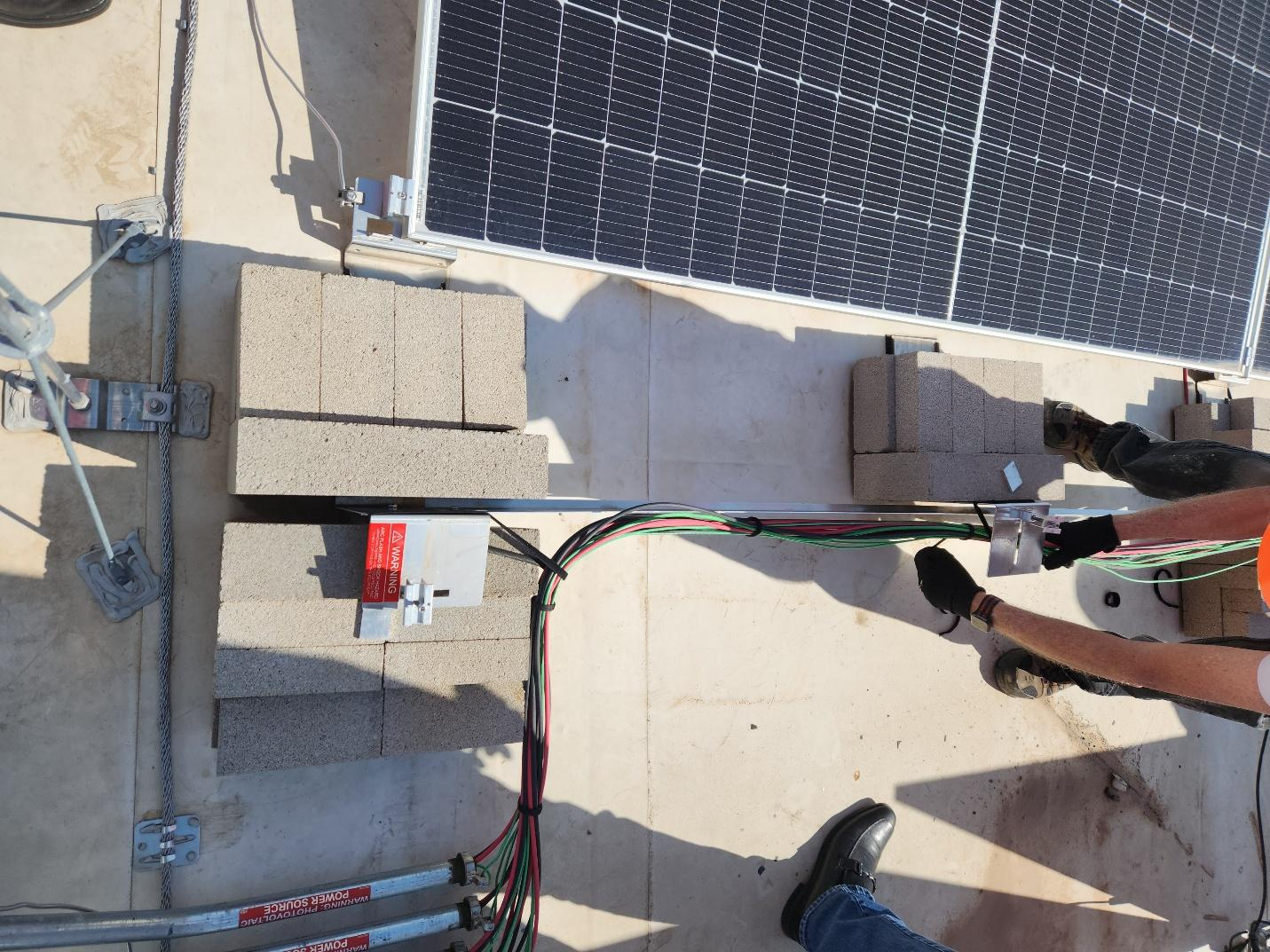
- DC Wire Management – The array’s wire management was not accomplished IAW the manufacturer’s published instructions.
- No actual commissioning checklist or report was provided.
- Members of the solar installation crew were no longer available for an interview.
The following steps consisted of:
- Engaging Bill Brooks of Brooks Engineering to conduct a forensic inspection. Known as the "Fire Guy" in the PV industry, Bill Brooks, PE, has led the way to understanding what causes fires in PV systems.
- Contact representatives from the various equipment manufacturers and invite them to participate in the forensic inspection. The inverter and RSD manufacturer agreed to have the RSD representative their collective participation.
The Risks of Incorrect Inverter Connections & Understanding DC Wire Management
The following summarizes the observations and results of the forensic inspection:
- Inverter 1 was the only inverter to power up.
- Inverter 2 could not power up.
- The actual wiring of DC strings did not correspond to the provided one-line diagram. Strings PVS 01-01 - 05 were to be wired into Inverter 1, and strings PVS 02-01 - 05 were to be wired into Inverter 2.
- The inspection of the inverters indicated that only two of the 10 DC string circuits were wired correctly.
- Identifying why the remaining DC strings were reading 0V DC at the inverter. It was known that at least two or three DC strings had been damaged in the fire.
- String PVS 02-05 positive homerun should have been landed into Inverter 2, but was landed into Inverter 1. PVS 01-05 was landed in Inverter 2. The cross-wiring of the inverters created a wiring scenario that led to other wiring mistakes.
- Inspecting the strings PVS2-01-04 connected to inverter 2 determined that the string labeling was incorrect and did not correspond to the infrared report referenced by the EC.
- It was discovered that strings PVS2-01 and PVS2-02 were wired in series and connected to Inverter 2. This meant that the circuit had 36 modules wired in series, as opposed to 18. The open-circuit voltage was 1782 Vdc, which damaged the inverter, which was rated for a maximum of 1000 Vdc. This was the reason Inverter 2 never powered up and the cause of the fire.
- Strings PV2-03 and PV02-04 were wired together on the roof.
Lessons Learned from Forensic Inspections: Engaging Experts for Better Outcomes
The forensic inspection determined that all the mistakes found were easily preventable. The claim that these strings could not be evaluated until the inverters were powered up from the utility side is categorically false. This claim was made by technicians who clearly were not qualified and did not understand the equipment they were working with. There is no excuse whatsoever for these wiring mistakes.
The fire that occurred at the facility was the result of several critical wiring mistakes. These wiring mistakes caused equipment damage in the array, which eventually led to a fire in the section of solar panels labeled Inverter 2, String 5. All these wiring mistakes were easily preventable and showed a lack of experience on the part of the installers.
Best Practices for Solar Installations: Ensuring Safety and Efficiency
In conclusion, it is crucial that you review the qualifications of not only the EC but also any solar installer who claims to have solar installation experience. Specifically, the following:
- What training and certifications do they have?
- Are they NABCEP certified?
- How many installations have they completed?
- What type of insurance do they have?
- Can they provide references?
- How is the installation work inspected as it progresses?
- How is the commissioning process conducted and documented?
- Will an O&M manual be provided?
- Will As Built drawings be provided?
- Is an annual service plan provided?
